A 3-DOF robotic wrist,
engineered from zero.
A concentric-geared ball wrist and custom gearbox for a competition rover arm — driven to a 15:1 reduction and roughly 30% lighter across ten design iterations, then machined, printed, and assembled by hand.
- 3DOF
- Degrees of freedom
- 15:1
- Gear reduction
- −30%
- Mass reduction
- $250
- of a $500 budget
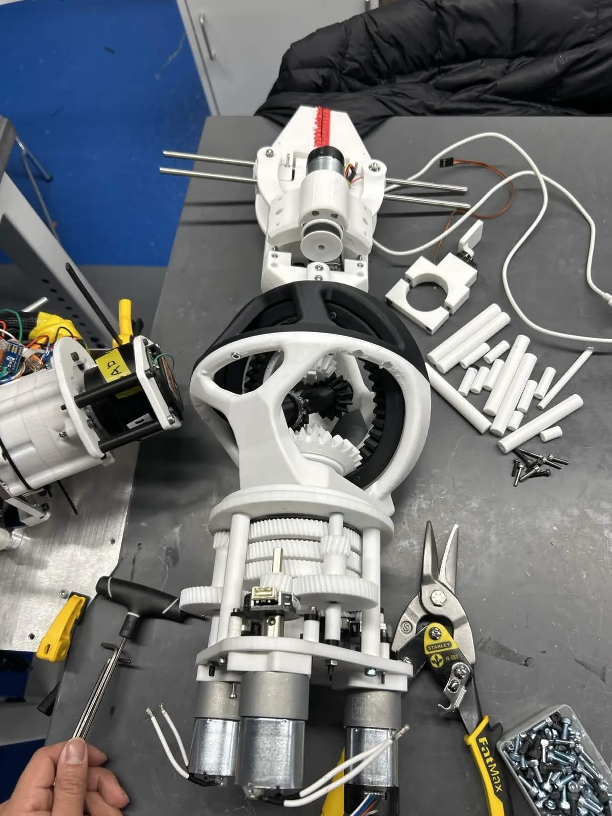
Bringing the wrist to life
Renders prove intent. This proves function — all three axes articulating under motor power.
Bench test — three-axis articulation under power
Mass at the end of an arm is the enemy. Every gram the wrist adds multiplies the torque demand through every joint upstream — so the wrist had to deliver three degrees of freedom and a 15:1 reduction in the smallest, lightest, most serviceable package possible.
Kinematics
Three degrees of freedom from a compact concentric ball-wrist layout.
Torque
15:1 reduction to drive the wrist under load at the arm's end.
Packaging
Three gearmotors and three encoders inside one short housing.
Environment
Survive the Utah desert — fine, abrasive Mars-analog dust everywhere.
Serviceability
Field-swappable motors without tearing the whole gearbox down.
Budget & shop
$500 subsystem cap, built on student-shop CNC, water jet, and FDM.
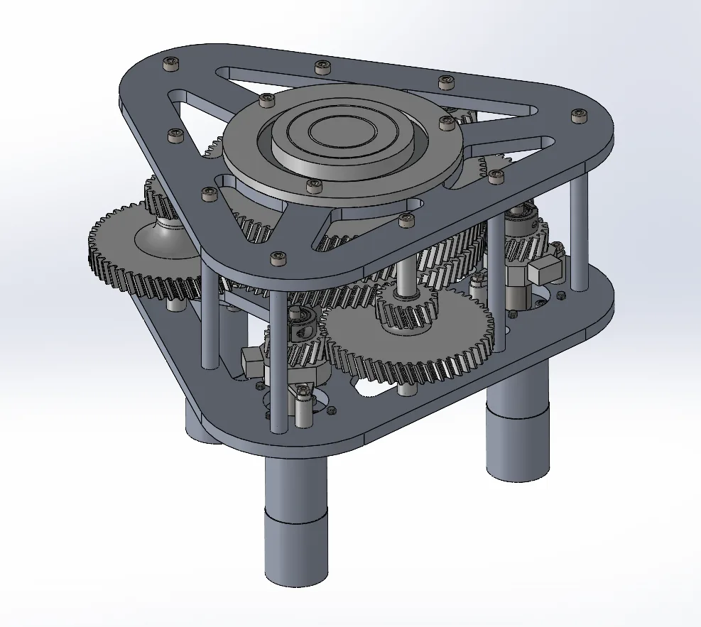
Too much of everything
The first architecture worked on paper and almost nowhere else. It was oversized and heavy, packed with material chasing rigidity the joint never needed, and it interfaced poorly with both the arm and the wrist it was meant to drive.
- Over-built for stiffness — mass with no payback
- Large footprint fought the end-of-arm packaging budget
- Weak, ad-hoc interfaces to the wrist and arm clamp
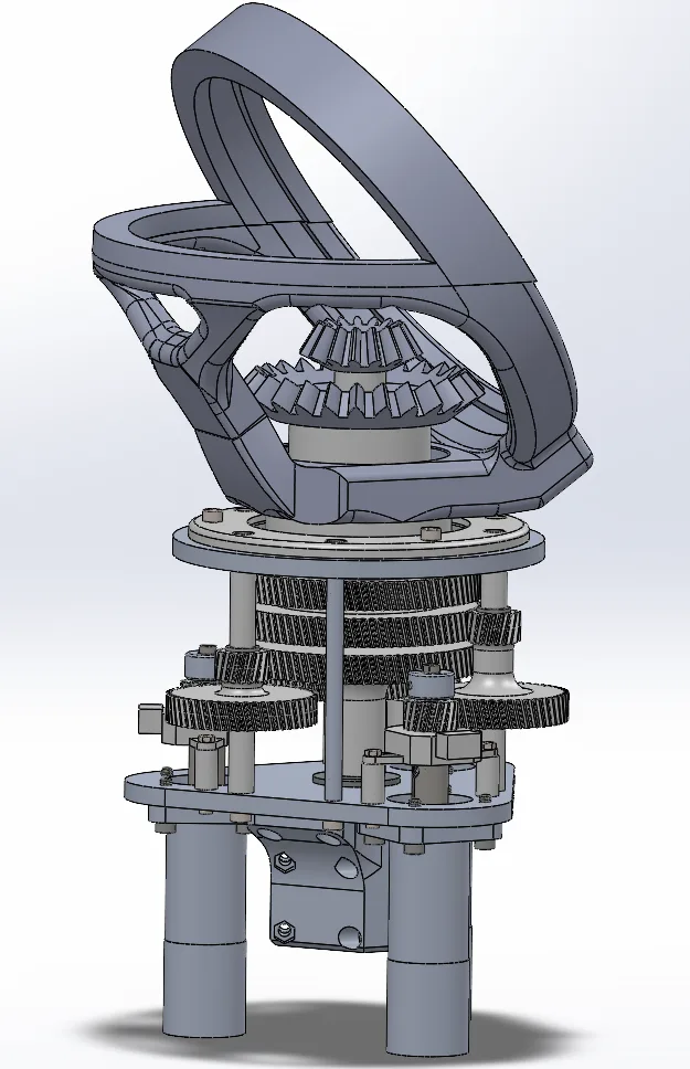
Lighter, tighter — still not done
Each review with senior engineers stripped another layer of excess. Lightening pockets opened up the structural plates, the footprint shrank, and the packaging started to resolve — but the gear train and interfaces still needed real refinement.
Ten-plus iterations, each reviewed and measured. The discipline of rapid, critiqued revision is what turned a heavy concept into a flight-worthy mechanism.
Ten iterations, one clean package
Helical and compound gearing to 15:1, standoff construction for repeatable assembly, an integrated dust cover, and roughly 30% less mass than where it started.
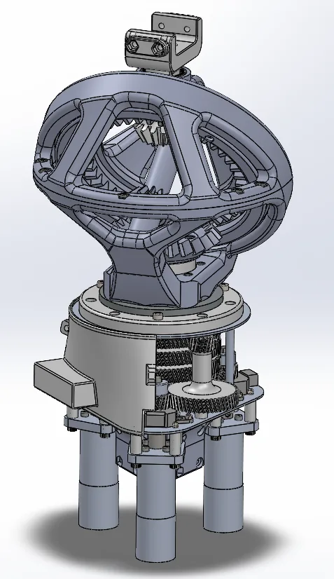
Helical gearing
~10% better load distribution and smoother engagement than spur.
Compound reduction
Stacked stages reach 15:1 while keeping the package short.
Standoff construction
Replaced bolt-and-spacer stacks for repeatable assembly.
Concentric power transmission
A section cut through the wrist's center plane. Three drive paths run concentrically through a single axis — the densest packaging problem on the arm, solved in one nested gear train.
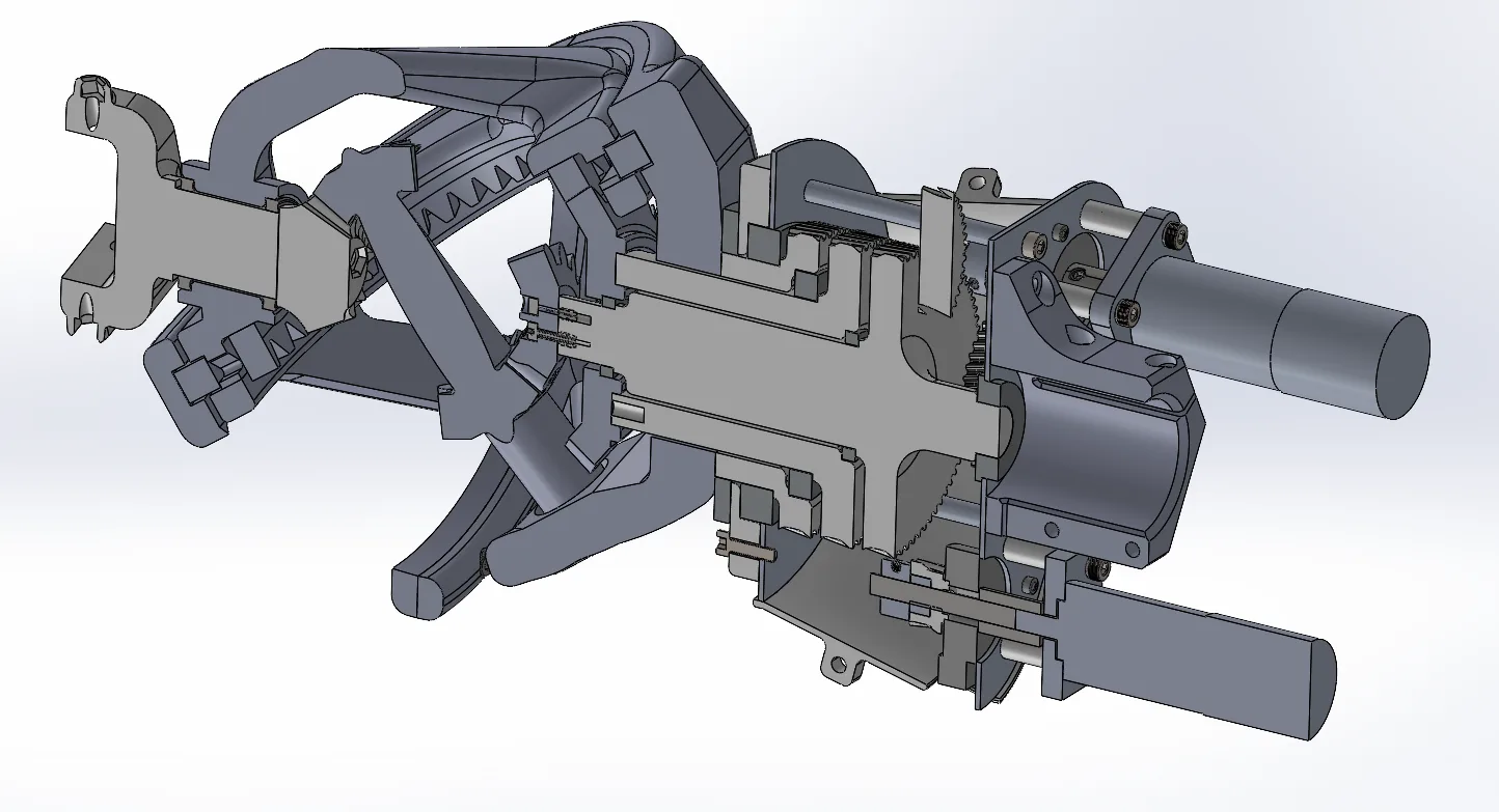
- 01
Concentric output
Three coaxial drive paths share one axis, feeding the wrist's degrees of freedom without splaying the package.
- 02
Helical stage
Angled teeth spread the load across more contact and run quieter under torque.
- 03
Compound reduction
Reductions stacked in series hit 15:1 while keeping the gearbox short enough to live at the arm's end.
- 04
Bearing interfaces
Located, preloaded interfaces keep the concentric shafts true under bending load.
I cut the metal myself
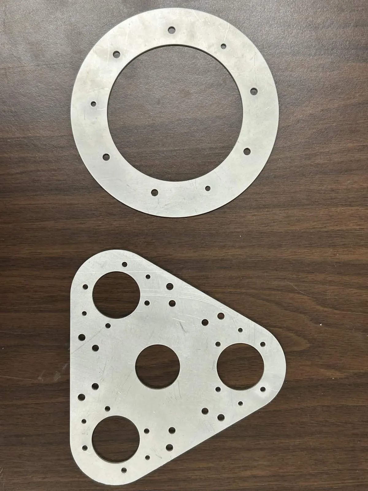
The design didn't stop at a render. I cut the structural plates from 6061 aluminum on the water jet, CNC-machined the precision interfaces, and FDM-printed the housing and dust cover — three physical prototype iterations on the way to a built assembly.
- Material
- 6061-T6
- Process
- Water jet
- Prototypes
- 3 builds
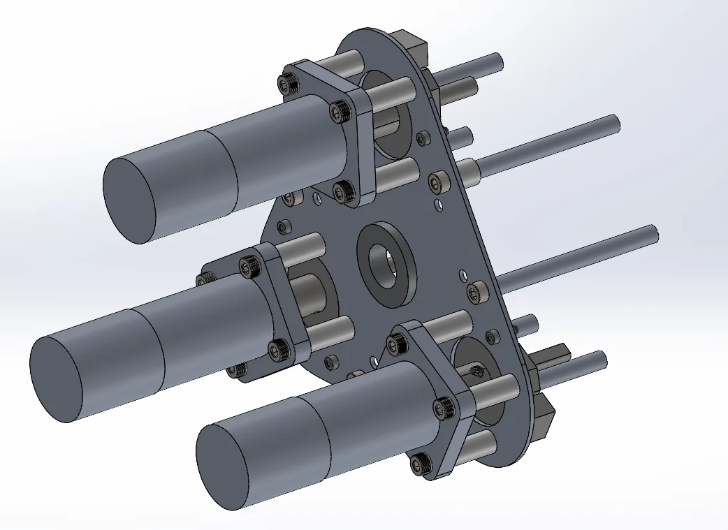
Built to be serviced in the field
Each drive motor rides on its own quick-release plate rather than a single monolithic base. A motor can be swapped between runs without disassembling the gearbox — modularity bought at almost no mass cost.
- Per-motor detachable mounting plates
- Field-swappable drives without a full teardown
- Standardized hardware across the assembly
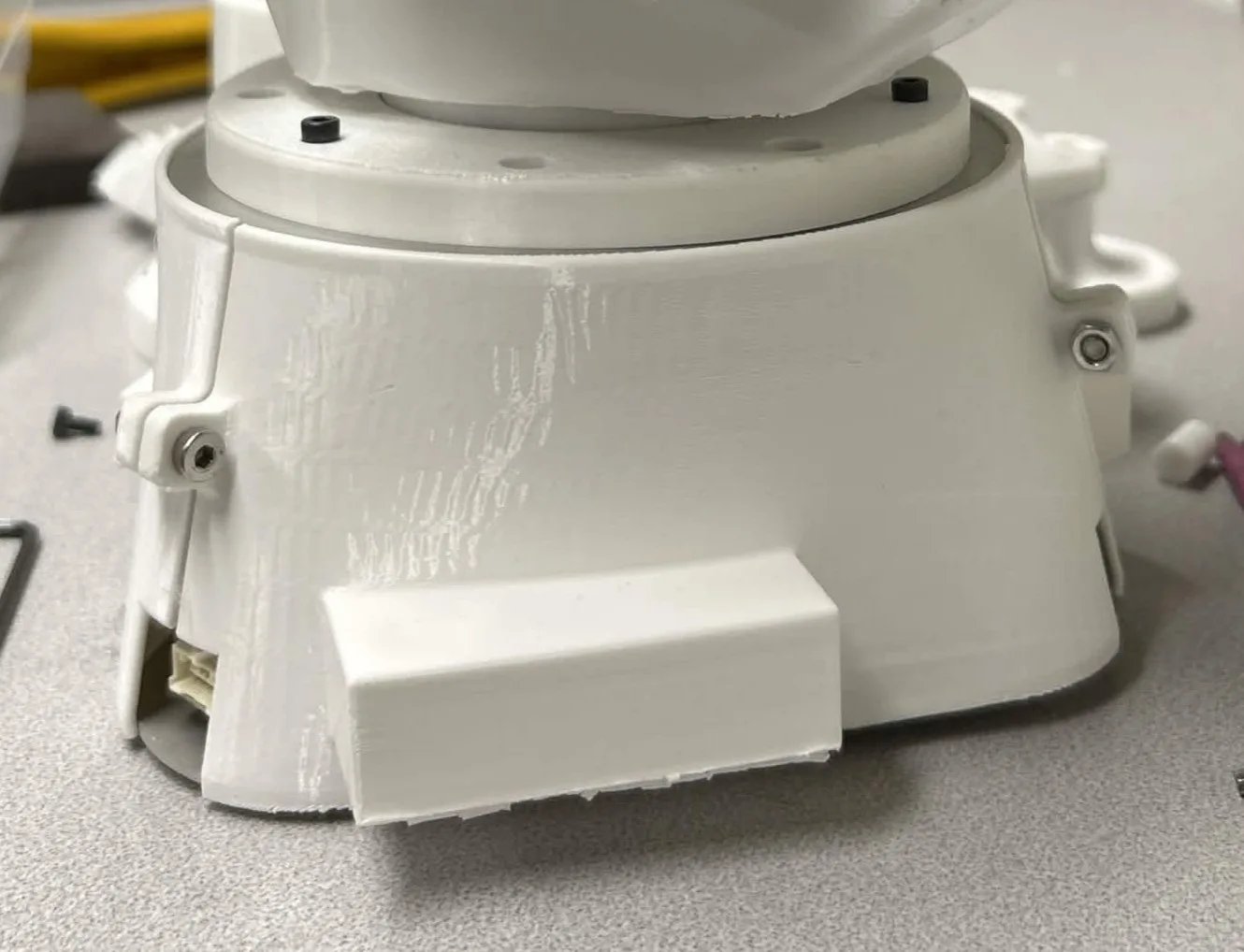
Sealed against the desert
URC runs in the Utah desert, a Mars analog where fine grit migrates into any open mechanism. A printed dust cover seals the concentric gear train against the debris that would otherwise accelerate wear and jam the wrist mid-task — sized for a clean, precise fit on the built hardware.
A flight-worthy wrist, half the budget, a third lighter
- 15:1
- Reduction achieved
- −30%
- Mass vs. first design
- $250
- Cost — half the budget
- 10+
- Reviewed iterations
What this demonstrates
What I took from it
A working system is the goal, but a manufacturable, serviceable one is the job. The operating environment is a design input — the dust cover is as much a part of the gearbox as the gears — and rapid, critiqued iteration is what compounds a rough concept into something that flies.